-

-

REPORT FORMAT

TUTORIAL SETTING OUT

TUTORIAL CURVE

TUTORIAL OF TRAVERSE SURVEY

Tutorial 1
a. Refer to Table 1a, calculate the final bearing for all station. 


Table 1a : Data of traverse


b. Refer to Table 1b and calculate :
  i. Latitude and Departure for all station.
 ii. Correction of latitude and departure
iii. Final latitude and departure.
iv. Calculate coordinate if coordinate of station 1 is (500,500)
Table 1b: Final Bearing


Tutorial 2


Table 2

Refer to Table 2;
a. Calculate the final bearing for all station.

b. Calculate;
  i. Latitude and Departure for all station.
 ii. Correction of latitude and departure
iii. Final latitude and departure.
iv. Calculate coordinate if coordinate of station 1 is (1000,1000)

Refer formula;


TUTORIAL MASS HAUL DIAGRAME

TUTORIAL AREA AND VOLUME

TUTORIAL TRAVERSE THEODOLITE

TUTORIAL LEVELING

SETTING OUT


CURVE


MASS HAUL DIAGRAM


AREA and VOLUME


EDM


TRAVERSE THEODELITE


Introduction
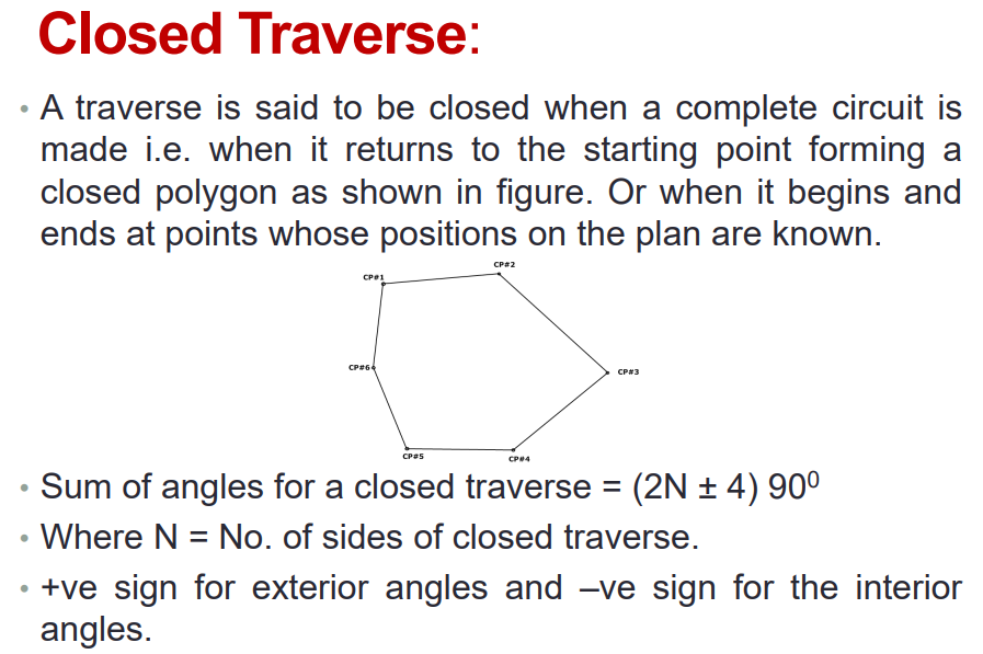
A method of establishing control points, their position being determined by measuring the distances between the traverse stations (which serve as control point) and the angles subtended at the various stations  by their adjacent stations.


Principles of Theodolite
The principles of the theodolite are that a beam of light travels in a straight line, and that when you know the length of one side of a triangle and the angles of the corners as measured by reflecting beams of light then you can precisely map features on the ground both horizontally and vertically.


Type of Theodolite

                                      Figure 1 : Type of Theodolite


Vernier Theodolite
The vernier theodolite is a also know as a transit. In a transit theodolite or simply transit the telescope can be rotated in a vertical plane. Earlier versions of theodolite were of the non-transit type and are obsolete now. 

Two view of a vernier theodolite are in Figure 2. The instrument details vary with different manufacturers but the essential parts remain the same.

 Figure 2 : Component of Vernier Theodolite


ABOUT SURVEY


Definition of Survey
Survey is an art and science of sighting and reconnaissance, inspect situation and measuring in order to produce map. 


Surveying is the art and science of making field measurement on or near the surface of the earth. Survey field measurement include horizontal and slope distance, vertical distance and the horizontal-vertical angle. In addition to taking measurement in the field, the surveyor can derive related distances and directions through geometric and trigonometry analysis (Barry F.Kavanagh).


Type of Survey

i. Geodetic Survey are to determine very precisely the relative or absolute positions on the earth surface of a widely separated points


ii. Plan Survey Remote sensing, mapping and charting depending on plane surveying of fixed reference points, like monuments, longitude and latitude coordinates; magnetic effects, and relative velocity of Earth points to each other.

Table 1 : Difference between Plain Survey and Geodetic Survey


Principle of Survey

Basic Principles of Surveying is a fundamental rule to always work from the whole to the part. To locate a new station by at least two measurements (linear or angular) from fixed reference points. This implies a precise control surveying as the first consideration followed by subsidiary detail surveying.


This means, when an area is to be surveyed, first a system of control points is to be established covering the whole area with very high precision. Then minor details are located by less precise methods.


Uses of Survey

Surveying is the scientific technique to determine the position of points and angles & distances between them. The process of surveying is used to fulfill various purposes. It is necessary for making map, planning a project etc.


Engineering Survey


The survey which are carried out for determination of quantities or to afford sufficient data for designing engineering work such as roads, railways, dams, sewage disposal, and construction work generally. based on boundaries mark, beach mark, triangulation monument, GPS monument and have vertical and horizontal control.  

Figure 1 : Engineering Survey


Cadastral Survey

The survey which are generally plotted to a larger scale than topographical survey and arc carried out for fixing the property lines, calculation of area landed properties and preparation of revenue maps of states. A survey for the preparation of defining legal property boundaries. To produces a plans of property boundaries for legal purpose, such as determination of boundaries mark, resurvey for land acquisition, subdivision etc.  

Figure 2 : Cadastral Survey


Hydrographic Survey

The science of measurement and description of features which affect maritime navigation, marine construction, dredging, offshore oil exploration/offshore oil drilling and related activities.


Figure 3 : Hydographic Survey


Topographic Survey
The survey that gathers data about the elevation of points on a piece of land and presents them as contour lines on a plot. The purpose of a topographic survey is to collect survey data about the natural and man-made features of the land, as well as its elevations.


Figure 4 : Topographic Survey


Astronomy Survey
A general map or image of a region of the sky which lacks a specific observational target. Alternatively, an astronomical survey may comprise a set of many images or spectra of objects which share a common type or feature. Surveys are often restricted to one band of the electromagnetic spectrum due to instrumental limitations, although multi-wavelength surveys can be made by using multiple detectors, each sensitive to a different bandwidth.


Figure 5 : Astronomy Survey


 Global Positioning System Survey (GPS)
GPS is a highly accurate navigation system using signals from satellites to determine a location on the Earth's surface, irrespective of weather conditions. It is dependent on GPS satellites high above the Earth which transmit signals containing the time and location of the satellite


Figure 6 : Global Position System Survey


Photogrammetry Survey 

Photogrammetry is the practice of determining the geometric properties of objects from photographic images. Is the making of precise measurements from photographs; the making of maps from photographs, especially from aerial surveying

Figure 7 : Photogrammetry Survey


Remote Sensing Survey
Remote sensing is the acquisition of information about an object or phenomenon without making physical contact with the object and thus in contrast to on-site observation, especially the Earth. Remote sensing is used in numerous fields, including geography, land surveying and most Earth Science disciplines .


Figure 8 : Remote Sensing Survey


LEVELING


Definition of leveling
Leveling is the process use to determine a difference in elevation between two point.

A process of determining the height of one level relative to another. It is used in surveying to establish the elevation of a point relative to a datum, or to establish a point at a given elevation relative to a datum. 


Principle of leveling
To obtain horizontal line of sight with respect to which vertical distances of the points above or below this line of sight are found. 


Figure 1 : Principle of leveling


Purpose of leveling (general usage)

To find the elevations of given points with respect to a given datum. To establish points at given elevations or different elevations with respect to the given or assumed datum.


Leveling term

a. Bench Mark (BM)
point with known height above mean sea level (or other reference datum). These are permanent points (e.g. unchanged by weather conditions) and are provided by the Department of Lands and Surveys.
 
 Figure 2 : Bench Mark


b. Temporary Bench Mark (TBM)
a point of known height above a pre-defined level. This level is not absolute and is defined locally by the surveyor for the purpose of the survey. Based on the TBM the survey may then later be reduced to absolute levels if the level of TBM is known.   


  Figure 3 : Temporary Bench Mark 


c. Back Sight (BS)
first staff reading taken immediately after setting up the instrument. 
 Figure 4 : Backsight (BS)


d. Foresight (FS)
Last staff reading taken before moving the instrument to another location.


Figure 5 : Foresight (FS) 


e. Intermediate sight (IS)

All readings taken between a BS and a FS. 

  Figure 6 : Intermediate sight (IS)


f. Change point (CP)

A point that has back sight and fore sight reading.

Figure 7 : Change point (CP)


g. Reduced level (RL)

Reduced level is the vertical difference between the level point and datum line or the mean sea level. Reduced Level in surveying refers to equating elevations of survey points with reference to a common assumed datum. 


h. Datum

Reduced Level in surveying refers to equating elevations of survey points with reference to a common assumed datum.

 
i. Mean sea level (MSL)
Mean sea level is established by taking the average height of tides in the sea over a very long period (generally 18years). Mean sea level or MSL is used as datum level for all important surveys. 
Figure 8 : Mean sea level (MSL) 


Type of  level instrument

Figure 9 : Type of  level instrument

 a. Automatic level  
It uses a compensating system of prisms suspended in the telescope to ensure that the line of collimation is horizontal. Simply center the pill bubble as above. 

b. Digital level 
That reads and records the staff for you (at much greater cost).

c. Tilting level  
The telescope is hinged. An accurate bubble tube (usually with a split bubble viewer) is used for accurate leveling of each shot. The Tilting level replaced the Dumpy level which required 3 foot screws to be adjusted for each shot.


Instruments use in leveling

Figure 10 :  Instruments use in leveling


Temporary adjustment for level 
This adjustment are performed at every setup of instrument.  
  • Setting up of leveling : This operation includes fixing the instrument on the tripod and also approximate leveling by leg adjustment.
  • Leveling up : Accurate leveling is done with the help of foot screws and by using plate levels. The object of leveling up the instrument is to make its vertical axis truly vertical.
  • Elimination of parallax ( Focusing of the eye peace
    &
    Focusing of object glass) : If the image formed by the objective does not lie in the plane of the cross hairs, there will be a shift in the image due to shift of the eye. Such displacement of image is termed as parallax. Parallax is removed in two stages.
         
Two peg test

A two peg test is a test for error within a surveying level. This test gives a fairly accurate check for the amount of collimation error. Collimation error is the difference between what the level hairs in the scope say is level, and what is actually level. 


Figure 11 :  Two peg test

  • Setup and mark on the ground (with wooden pegs driven into the earth, or roofing nails in tar) two point some 30m apart. Set up the the level exactly mid-way between them. 
  • Take measurements of back sight and foresight for this first setup. The height difference dh1 will be free of the effects of collimation error.
  • Next, move the level to a position just beyond the fore staff position (about 10m).
  • Then repeat the readings.  
Example:
 
A = (a2 - 3e)
B = (b2 - e)
The actual correction = (a2 - 3e)    -  (b2 - e)
                                   = (7.86 - 3e) -  (6.36 - e) 
                                   = 1.5 - 2e    ...............equation (i)
The actual difference =    a1 -  b1
                                   = 3.75 - 4.25 
                                   = - 0.5         ................equation (ii)

∴ equation (ii) = equation (i)
                - 0.5 = 1.5 - 2e
                   2e  = 2
                     e  = 1m/jarak


actual reading at A (a2) = 7.86 - 3e
                                       = 7.86 - 3(1)
                                       = 4.86
actual reading at B (b2) = 6.36 - e
                                       = 6.36 - (1)
                                       = 5.36


Inverse staff reading


Figure 12 :  Inverse staff reading


Series level procedure, booking and calculation

Figure 13 :  Series level data and procedure

  • The instrument (L1) is set up approximately ∓5m away from the BM and a staff reading to the nearest 0.001m is observed and booked. 
  • The staff is move to IS point A and B. If any levels are required to objects in the immediate area of the level, then intermediate levels are taken and booked in the intermediate sight column.
  • The staff is moved to the FS position point C and again the observation is observed to 0.001m and booked. (example of the booking sheet)
      • Care should be taken that the BS distance is equal or nearly equal to the FS distance.
      • This point C is referred to as a change point and must be a firm physical object.
  • The level is then moved to (L2) approximately ∓5m from staff, as shown in the diagram above. BS reading is then observed to the staff at point C to the nearest 0.001m. 
  • The staff is move to IS point D.
  • The staff then moved to the next change point E and a FS reading taken.
  • The level is then moved to (L3) approximately ∓5m from staff, as shown in the diagram above.
  • These steps are repeated until the end of the levelling run is reached - the last point (FS) should always be a point of known RL. 


a. Rise and fall method

Adjustment          = 48.71 - 48.701
                             = 0.009

Total BS is 3 ∴    =  0.009 / 3
                             = 0.003 per station 

Arithmetic check
Σ (BS) - Σ (FS) = 6.962 – 8.131 = - 1.169m 
Σ (RISES) – Σ (FALLS) = 1.515 – 2.684 = - 1.169m  
LAST (RL) – FIRST (RL) = 48.701 – 49.87 = -1.169m


b. Height of collimation method (HOC)


Adjustment          = 48.71 - 48.701
                             = 0.009

Total BS is 3 ∴    =  0.009 / 3
                             = 0.003 per station 

Arithmetic check
Σ (BS) - Σ (FS) = 6.962 – 8.131 = - 1.169m 
LAST (RL) – FIRST (RL) = 48.701 – 49.87 = -1.169m


Longitudinal Section and Cross Section Procedure 


Figure 14 : Longitudinal Section and Cross Section Design. (longitude distance is option)


 Figure 15 : Longitudinal Section and Cross Section procedure


  • Set-up a level at point of station 1 and perform temporary adjustment .(Refer Figure 15)
  • Set-up staff on BM/TBM as back sight (BS) and at point a1 until point c2 as intermediate sight (IS). Take and record the reading.
  • After that, move a level to station 2 and set-up it. Make sure the staff is still at point c3 as a back sight (BS) and the other staff move to point d1 until point e3 as  a intermediate sight (IS). Take and record the reading.  
  • Close at BM/TBM (started point) as a fore sight. 
  • During the process, make sure the bubble of staff and a level always center. 
  • Then, determine the adjustment reduced level.  
  • Calculate and plotting the result. 


Contouring using grid method procedure


Figure 16 : Contour using grid method design. (contour distance is option)


 Figure 17 : Contouring using grid method procedure


  • Set-up a level at point of station 1 and perform temporary adjustment .(Refer Figure 16)
  • Set-up staff on BM/TBM as back sight (BS) and at point a1 until point c2 as intermediate sight (IS). Take and record the reading.
  • After that, move a level to station 2 and set-up it. Make sure the staff is still at point c3 as a back sight (BS) and the other staff move to point d1 until point e3 as  a intermediate sight (IS). Take and record the reading.  
  • Close at BM/TBM (started point) as a fore sight. 
  • During the process, make sure the bubble of staff and a level always center. 
  • Then, determine the adjustment reduced level.  
  • Calculate and plotting the result.


 Figure 18 : Interpolation method calculation